.gif)

SOLAR TECHNOLOGY
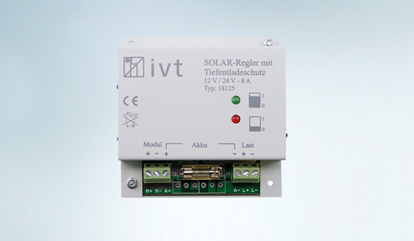
The solar controller is the most important link between the solar module and solar battery, and thus the central controlling element of an autarchic stand-alone system - as it manages the entire system.
At IVT you will find solar controllers with:
• Various controlling technology (serial, shunt, MPPT)
• Most effcient charging characteristics for all conventional battery types (lead-acid, lead-gel, lead-AGM, LiFePO4)
• Useful adjustment possibilities and functions for an individualized application
IVT solar controllers assure a controlled charging process with the best possible charging result and optimum battery maintenance.


ADVANTAGE OF IVT SOLAR TECHNOLOGY
VERSATILE / IN ALL RESPECTS
|
Whether stationary or on the go – the solar controllers by IVT are versatile in their application. For the most divers deploy- ment sites and all conventional battery types.
|
SAFE / WHEN IT MATTERS
|
Deep discharge protection with automatic load shut-off, overload and overheating protection as well as
non-return valve – with these and other protective functions you can always rely on your IVT solar controller.
|
PRECISE / DOWN TO THE SMALLEST DETAIL
|
For your valuable solar batteries an optimally controlled charging process is strictly required. Thanks to their precision IVT solar controllers always assure the best charging result.
|
ROBUST / RELIABLE & POWERFUL
|
The IVT solar controllers are so robust and well-worked that we grant a 3 year manufacturer warranty on all products.
|
INDIVIDUALIZED / CONSTRUCTION & PLANNING
|
Sometimes individualized solutions are necessary.
We gladly assist you in the planning of your solar system,
modify our products to meet your expectations or produce products according to your requirements.
|

AT ITS BEST: LOADING & ADJUSTMENT


COST-EFFECTIVE: SMALL & RELIABLE


USEFUL: THE ACCESSORIES


WELL-MATCHED
Put together a self-sufficient complete solution individually or let our technician configure it.


FLEXIBLE: USAGE & CHARGE
The individual IVT Power Stations offer you a self-sufficient power supply at any place and at any time. The integrated, high-quality 12 V lithium battery can be recharged in an extremely flexible way – either with solar power, in the vehicle or with 230 V mains voltage.


.jpg)

.jpg)


THINGS TO KNOW
Under the heading "things to know", we have put together helpful technical tips and general information on frequently asked questions. Do you have any other questions? Our competent team is always here to help. Simply get in touch.
Building a solar plant
|
.jpg)
Construction of an isle system with direct current and alternating
current consumers
An isle system for the independent supply with solar energy normally
consists of the following components:
COMPONENTS:
1. One (more) solar panel (s)
2. One solar charger (controller)
3. One (more) solar battery (ies)
4. Direct current consumers (e.g. 12 VDC LED light)
5. One inverter, if alternating current (AC) is needed
6. Alternating current consumers (e.g. 230 VAC light, TV set)
CONSTRUCTION AND DIMENSIONING:
• The solar panel (1) will be connected to the solar charger (2). The two cables (±) should be well dimensioned, in ordered to avoid power losses.
• The solar charger (2) will be connected to the solar battery (3) and eventually with the DC electrical consumers (4). The solar charger should be dimensioned at least 10 % higher than the maximum current of the solar panels.
• The battery cables and the cables to the consumers should always contain a fuse.
• The inverter (5) will always be connected to the battery (3), never directly to the solar charger (2),
as otherwise the solar charger could be damaged. This cable should also contain a fuse.
• To the inverter the 230 VAC electrical consumers may be connected.
• The safety regulations for electrical installations must be observed during installation.
With this isle systems you can build your individual energy source which you can use anywhere. All systems are fully functional after 3–7 days of charging time.
The solar batteries should be located in an enclosed and dry room.
|
Why do i need a solar controller
|
Solar controllers are used to feed solar energy in a regulated manner into a suitable energy storage system.
The radiative energy of the sun is converted into electrical energy by means of a solar cell respectively by a solar module.
The solar controller assures subsequently that this electrical energy is fed precisely and gently into a battery.
|
The Battery as energy storage system
|
Batteries are used to store electrical energy. Various technologies for manufacturing such energy storage systems are available on the battery market. Yet the typical characteristics are always the rated voltage (V) and the capacity (Ah).
Due to the cost factor the lead batteries are the predominant type used in the solar technology. For this reason, most solar controllers are specifically attuned for this battery type. Lithium Iron Phosphate batteries (LiFePO4) are energy storage systems of the newest generation and are well suitable for replacement of the existing lead battery systems, specifically due to their comparably low weight, as they have identical electrical properties.
For lead batteries a distinction is made between the following types:
• Classic, open lead-acid batteries
• Lead-gel batteries
• Lead-Absorbant-Glas-Matt batteries (lead-AGM batteries)
Especially when charging and discharging a battery it is important to adopt several criteria:
•The maximum charging current should be around 10 % of the battery capacity
• The cut-off voltage advised by the manufacturer must not be exceeded
• Deep-discharging the battery must be avoided
A solar controller must fulfil these criteria in order to allow for an optimum use of the battery and assure a long duty cycle of the often expensive energy storage system.
|
Solar cell / Solar module
|
A solar module consists of several interconnected solar cells and serves for converting the radiative energy of the sun into electrical
energy. Direct voltage is provided on the terminals of the radiated solar module. If the module is operated within a closed current
circuit direct current is available.
The subsequent diagram shows the idealized current/voltage characteristic of a solar module:
|
|
1 Short circuit point:
The solar module’s terminals are shorted, this means that the electrical resistance between the terminals is
extremely low.
The highest possible short circuit current IK of the solar
module flows at this point.
2 Maximum Power Point (MPP):
The solar module provides the highest possible power.
This is the product of current IMPP and voltage UMPP
in MPP.
3 Idle point:
At this point the solar module’s terminals are open, this
means that the electrical resistance between the
terminals is extremely high. The idle voltage of the
solar module can be measured on the terminals.
|
The working point moves between point 1 and 3, depending on which electrical consumer is connected to the solar module.
|
Charging methods
|
|
|
Charging with constant voltage (U-Ladung)
At the constant voltage charging the charging (end) voltage Uend will be kept constant during the entire charging process. As a result, at the beginning of the charging process the flowing current Imax is higher than at the end. With the decreasing current towards the end of the charging process the charging of the battery is gentle.
|
|

|
|
Charging by pulse-width-modulation (PWM)
When charging according to the pulse-width-modulation principle at the beginning of the charging process the battery is charged with maximum current Imax. As soon as the cut-off voltage Uend is reached, the current flow is stopped in order to avoid overcharging.
After this first charging step the battery is not fully charge most
of the time. A decrease of the battery voltage is to be expected. For this reason, the charging current restarts if the voltage Ustart falls short of a certain value. This process is repeated until the battery is completely full. The charging current phases become shorter as the battery fills up.
|
|
|
|
Types of charging regulation
|
.jpg)
|
Shunt regulation
During the charging process the solar module is connected with the battery via charge controller and charging current Icharge is fed from the solar module to the battery.
Yet, this process is only given if the solar voltage is higher than the required cut-off voltage of the battery. If this cut-off voltage is reached, this is recognized by the charge controller and the solar cell is shorted via contact S1.
Thus, the current flow from the solar module to the battery is stopped. With this, overcharging and damage
to the battery is prevented.
The entire current IK, provided by the solar module flows to the closed short circuit contact and will be converted to heat within the charge controller. On the solar module diagram (chart 1) the working point moves
to point 1 at full battery condition. During the charging process the working point is between point 1 and 2.
Advantages
• Fast regulation
• Simple switching mode
Disadvantages
• Not suitable for high power
• Solar power is not used in an optimum manner
|
.png)
.jpg)
|
Serial regulation
The solar module is connected with the battery which is to be charged by means of the charge controller and charging current Icharge is fed into the battery. Yet, this process is only given if the solar voltage is higher than
the required cut-off voltage of the battery. If the cut-off voltage is reached, the charge controller detects this and disconnects the battery by means of the switch contact S1. With this, the current flow to the battery is stopped. Thus, overcharging and damage to the battery is prevented.
On the solar module diagram (chart 1) the working point moves to point 3 at full battery condition.
During the charging process the working point is between 1 and 2.
Advantages
• Also suitable for higher power
• Simple switching mode
Disadvantages
• Solar power is not used in an optimum manner |
.png)
.jpg)
|
MPPT regulation
By virtue of the Maximum Power Point Tracker (MPPT) it is achieved that at all times the maximum
possible solar power Pmpp is converted into the maximum possible charging power Pbat for the connected
battery.
Pmpp = Pbat
Umpp • Impp = Ubat • Ibat
The MPPT function determines the working point of the solar panel at which the maximum solar power Pmpp
is available (chart 1: point 2). This maximum power is processed by the MPPT into the required battery
charging voltage Ubat and the corresponding charging current Icharge. Charge controllers without this function
are not able to process excessive voltage. Charge controllers with this function are able to also take
advantage of the excessive voltage.
Advantages
• Solar power is used in an optimum manner
• Suitable for solar modules with higher voltage
Disadvantages
• Complex switching electronic
|
|